Are you ready to dive into the world of music and discover the substance used by violin players? Or perhaps you’re curious about the mysterious suspicious trench coat tft from the game? Click on the links to uncover intriguing secrets and broaden your knowledge today!
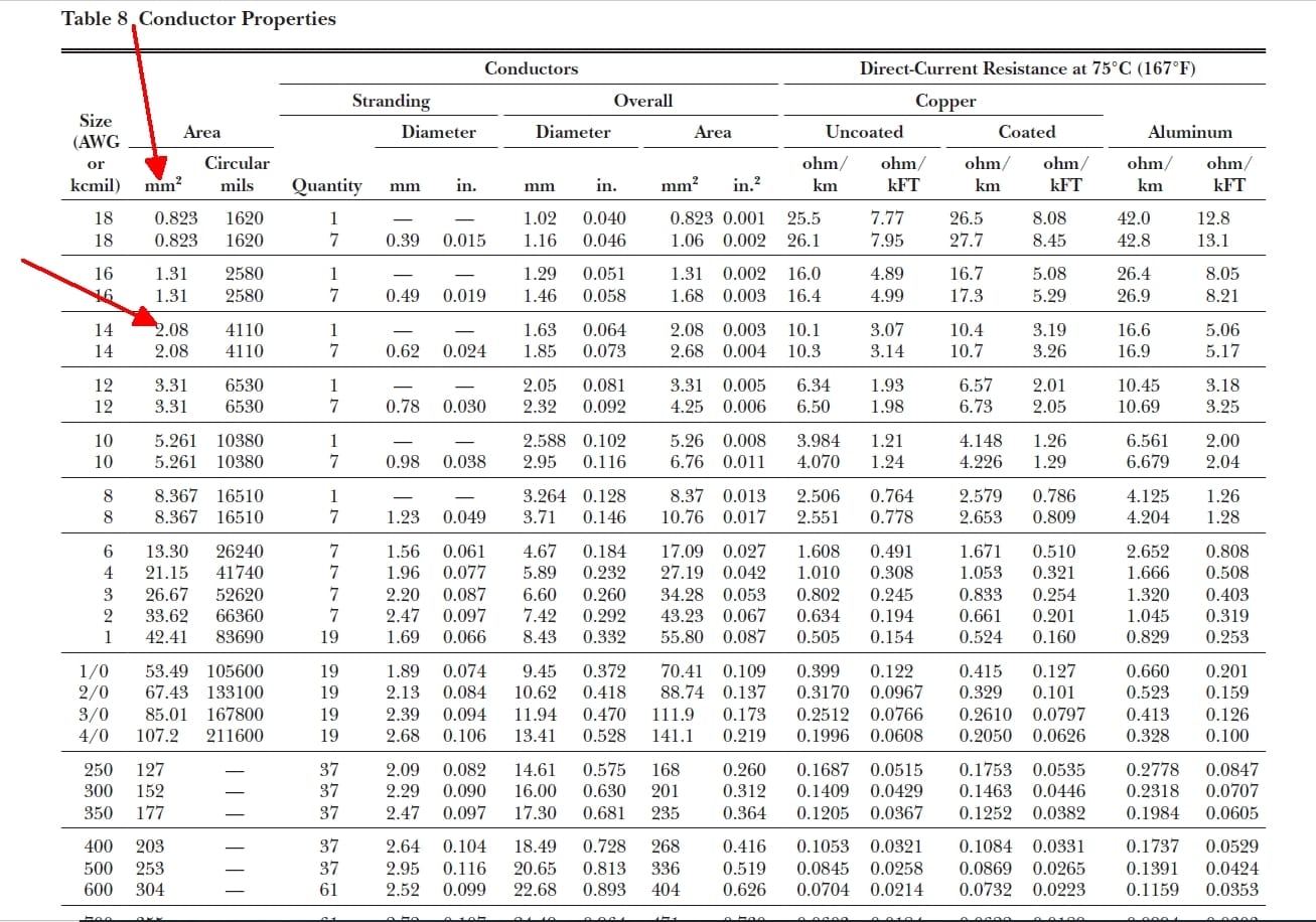
Understanding how much current your wiring can safely handle is crucial for any electrical project. This comprehensive guide decodes NEC Table 310.15(B)(16) (formerly 310.16), equipping you with the knowledge to calculate conductor ampacity and ensure electrical safety and efficiency.
Understanding Conductor Ampacity and the NEC
NEC Table 310.15(B)(16) is the electrician’s roadmap for safe conductor sizing, preventing overheating and electrical hazards. This table specifies the allowable ampacities (current-carrying capacity) for insulated conductors rated up to 2000 volts. Think of ampacity as the “speed limit” for electricity in a wire. Exceeding this limit can lead to overheating, insulation damage, and potentially, fire.
Why the Change from Table 310.16?
The shift from NEC Table 310.16 to 310.15(B)(16) in the 2020 NEC edition reflects code modernization. This reorganization streamlines Article 310, improving clarity and organization for easier application. The core principles remain the same, but the updated structure clarifies the conditions of use related to ampacity calculations.
Key Factors Influencing Ampacity
Several factors influence a conductor’s ampacity. Understanding these is crucial for correctly applying NEC Table 310.15(B)(16):
- Ambient Temperature: The surrounding air temperature significantly impacts a wire’s ability to dissipate heat. The table assumes an ambient temperature of 30°C (86°F). Higher temperatures require derating.
- Conductor Material: Copper and aluminum are common conductor materials. Copper offers better conductivity and thus generally higher ampacity for the same size.
- Insulation Temperature Rating: The insulation around a wire has a temperature limit. Common ratings are 60°C, 75°C, and 90°C. Higher ratings allow for higher ampacities.
- Number of Conductors in a Raceway: Bundling multiple conductors together restricts heat dissipation. The table assumes no more than three current-carrying conductors in a raceway. More conductors necessitate derating.
Using NEC Table 310.15(B)(16): A Step-by-Step Guide
This section provides a clear, step-by-step approach to using the table:
Determine Conductor Insulation Temperature Rating: Check the markings on the wire’s insulation for the temperature rating. This determines the correct column to use in the table.
Identify Wire Gauge: Determine the wire’s size in American Wire Gauge (AWG) or circular mils (kcmil). Locate the corresponding row in the table.
Locate the Intersection: Find the cell where the row (wire gauge) and column (temperature rating) intersect. This cell contains the allowable ampacity for that specific wire under standard conditions.
Adjust for Ambient Temperature: If the ambient temperature is higher than 30°C (86°F), refer to NEC Table 310.15(B)(2)(a) for correction factors. Multiply the ampacity from step 3 by the appropriate correction factor.
Adjust for Bundled Conductors: If more than three current-carrying conductors are bundled in a raceway, apply the derating factors from NEC Table 310.15(B)(3)(a) to the adjusted ampacity.
Never Exceed Ampacity: The current flowing through the conductor should never exceed the calculated ampacity. Always select the next larger standard conductor size if your calculated load exceeds the ampacity of the initially chosen wire.
Why Accurate Ampacity Calculations are Crucial
Inaccurate ampacity calculations can lead to overheated conductors, insulation failure, and potentially catastrophic fires. Properly applied, NEC Table 310.15(B)(16) serves several critical purposes:
- Ensuring Electrical Safety: Proper ampacity calculations prevent overheating, minimizing the risk of fire and electrical hazards.
- Optimizing System Performance: Correctly sized conductors minimize energy loss due to resistance, improving efficiency and reducing energy costs.
- Extending Equipment Lifespan: Avoiding overloading increases the lifespan of electrical equipment, preventing premature failures.
- Maintaining Code Compliance: Adhering to NEC guidelines ensures compliance with electrical codes, avoiding fines and legal issues.
Advanced Considerations
While this guide covers the basics, some advanced concepts require further exploration:
Parallel Conductors
For very high current requirements, multiple smaller conductors can be run in parallel. However, this requires specific calculations and adherence to NEC guidelines.
Conduit Fill
The number of conductors within a conduit is limited by conduit fill calculations. Overfilling a conduit can restrict heat dissipation and lead to overheating.
Voltage Drop
Over long distances, voltage can decrease along the conductor. Voltage drop calculations ensure that the voltage at the load remains within acceptable limits.
Staying Up-to-Date
Ongoing research and evolving technology may lead to future revisions of NEC Table 310.15(B)(16). Always consult the latest edition of the NEC for the most accurate and up-to-date information. Some experts believe that future research may focus on more granular factors influencing ampacity, such as humidity and specific installation environments.
Seek Professional Guidance
While this guide provides a solid foundation, consulting a qualified electrician is crucial for complex electrical installations. Their expertise ensures that your wiring meets all necessary codes and safety standards. Remember, electrical safety should always be the top priority.
- Unlock Water’s Symbolism: A Cross-Cultural Exploration - April 20, 2025
- Identify Black and White Snakes: Venomous or Harmless? - April 20, 2025
- Unlocking Potential: Origins High School’s NYC Story - April 20, 2025


