This comprehensive guide provides a deep dive into NEC Table 310.15(B)(16) (formerly 310.16), your essential resource for determining the safe current-carrying capacity, or ampacity, of insulated conductors. Understanding and correctly applying this table is paramount for ensuring electrical safety, preventing overheating, and guaranteeing the reliable operation of your electrical systems.
Understanding Conductor Ampacity
NEC Table 310.15(B)(16) dictates the allowable ampacities of insulated conductors rated 0 through 2000 volts, crucial for preventing overheating and electrical hazards. This section breaks down the core concepts of ampacity and its significance.
What is Ampacity?
Ampacity is the maximum amount of electrical current a conductor can safely carry continuously under specific conditions without exceeding its temperature rating. Exceeding a conductor’s ampacity can lead to insulation degradation, overheating, and potentially catastrophic fire hazards. Therefore, precise ampacity calculations are essential for any electrical installation.
Why is Ampacity Important?
Correctly applying NEC 310.15(B)(16) ensures compliance with safety standards, prevents equipment damage, and optimizes electrical system performance. Properly sized conductors ensure efficient power distribution, minimize energy loss, and prevent nuisance tripping of overcurrent protective devices.
Decoding NEC Table 310.15(B)(16)
Understanding ambient temperature, conductor material (copper vs. aluminum), and the number of conductors in a raceway are essential for accurate ampacity calculations using 310.15(B)(16). This section provides a step-by-step guide to navigating the table and applying its provisions correctly.
Table 310.15(B)(16) Title and Scope
Title: Allowable Ampacities of Insulated Conductors Rated 0 Through 2000 Volts, 60°C Through 90°C (140°F Through 194°F), Not More Than Three Current-Carrying Conductors in Raceway, Cable, or Earth (Directly Buried), Based on Ambient Temperature of 30°C (86°F).
Scope: This table applies to insulated conductors used in common wiring scenarios, including raceways, cables, and direct burial installations. It covers conductors rated up to 2000 volts and assumes an ambient temperature of 30°C (86°F).
Key Factors Influencing Ampacity
Conductor Material: Copper conductors generally possess higher ampacity than aluminum conductors of the same size due to their superior conductivity.
Ambient Temperature: Higher ambient temperatures necessitate derating the conductor’s ampacity. Section 310.15(B)(2)(a) provides correction factors for temperatures exceeding 30°C (86°F).
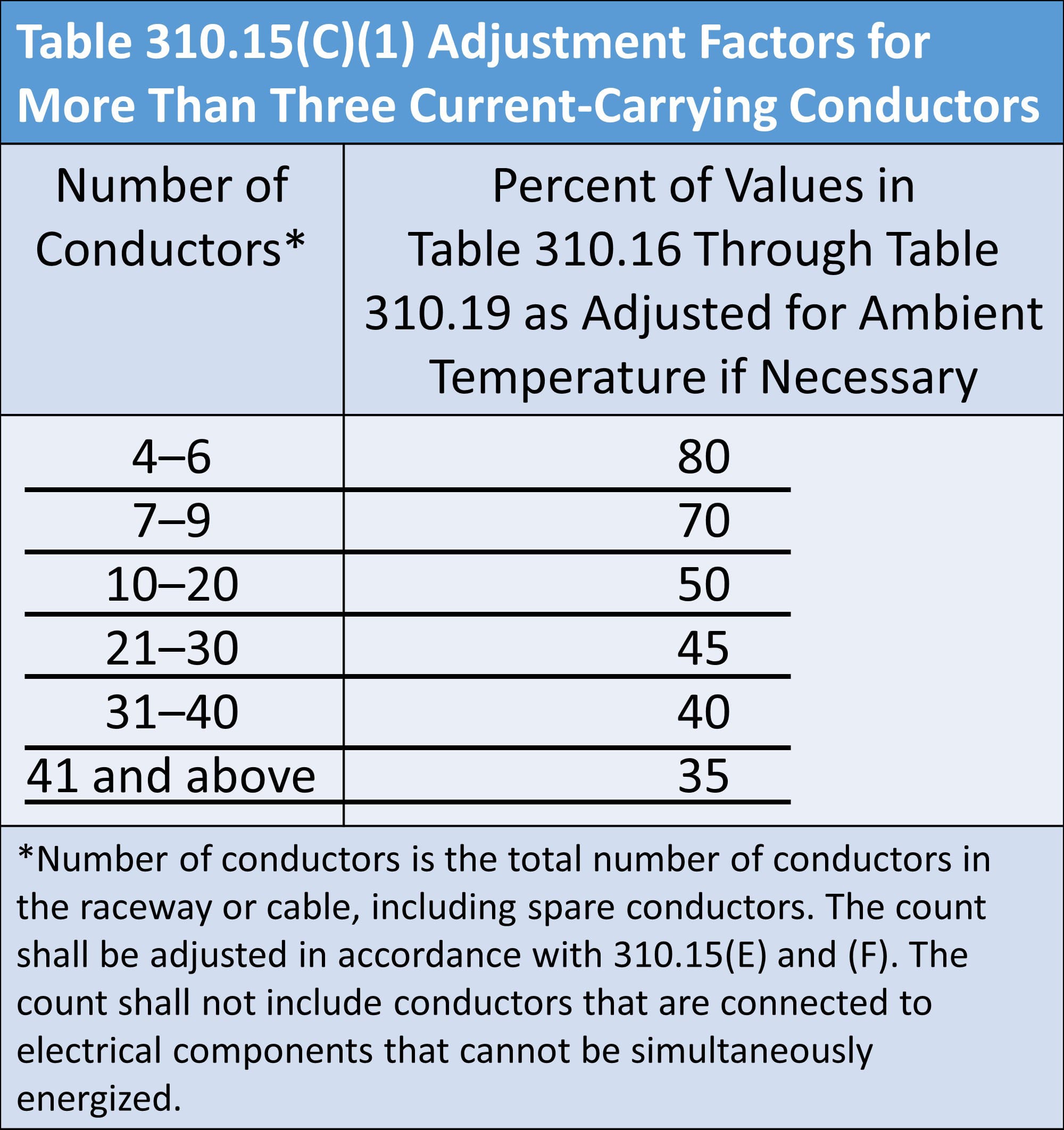
Number of Current-Carrying Conductors: When multiple conductors are bundled within a raceway, their combined heat generation increases. Section 310.15(B)(3)(a) mandates derating factors for more than three current-carrying conductors.
Insulation Temperature Rating: Conductors with higher temperature rated insulation, such as 75°C or 90°C, can handle higher ampacities compared to 60°C rated insulation.
Conductor Size (AWG or kcmil): Larger conductors, designated by lower AWG numbers or higher kcmil values, have greater cross-sectional areas and, consequently, higher ampacity ratings.
How to Use Table 310.15(B)(16)
Determine Conductor Material: Identify whether the conductor is copper or aluminum.
Determine Ambient Temperature: Establish the ambient temperature of the installation environment.
Determine Number of Conductors: Count the number of current-carrying conductors within the raceway or cable.
Determine Insulation Temperature Rating: Note the temperature rating of the conductor’s insulation (e.g., 60°C, 75°C, 90°C).
Locate Conductor Size: Find the appropriate AWG or kcmil size of the conductor in the table.
Determine Ampacity: Read the corresponding ampacity value for the given conductor material, insulation temperature rating, and size.
Apply Correction Factors (If Necessary): If the ambient temperature exceeds 30°C (86°F) or if there are more than three current-carrying conductors, apply the appropriate correction factors as outlined in NEC 310.15(B)(2)(a) and 310.15(B)(3)(a), respectively.
Real-World Applications and Examples
This section provides practical scenarios and examples to illustrate the application of NEC Table 310.15(B)(16).
Example 1: Wiring a Kitchen Circuit
Let’s say you’re installing a new 20-amp, 120-volt circuit in a kitchen where the ambient temperature is expected to reach 40°C (104°F). You plan to use copper conductors with 90°C rated insulation in a cable containing three current-carrying conductors.
Initial Ampacity: From Table 310.15(B)(16), a 12 AWG copper conductor with 90°C insulation has an ampacity of 30 amps.
Ambient Temperature Correction: Referring to Table 310.15(B)(2)(a), the correction factor for 40°C is 0.82.
Corrected Ampacity: Multiply the initial ampacity by the correction factor: 30 amps * 0.82 = 24.6 amps.
Conductor Selection: Since the corrected ampacity (24.6 amps) is greater than the circuit rating (20 amps), a 12 AWG copper conductor is suitable for this application.
Example 2: Wiring Multiple Conductors in a Conduit
Imagine you are running six 12 AWG copper conductors with 75°C rated insulation through a conduit in a 30°C ambient temperature environment.
Initial Ampacity: Table 310.15(B)(16) lists the ampacity of a 12 AWG copper conductor with 75°C insulation as 25 amps.
Derating Factor: Table 310.15(B)(3)(a) stipulates a derating factor of 80% for six conductors.
Corrected Ampacity: Multiply the initial ampacity by the derating factor: 25 amps * 0.80 = 20 amps.
Conductor Selection: This calculation suggests that 12 AWG conductors may be suitable, provided the total circuit load does not exceed 20 amps after any ambient temperature corrections are applied.
Related NEC Articles and Considerations
Beyond the chart: This guide delves into the nuances of 310.15(B)(16), including correction factors, exceptions, and its relationship to other NEC articles.
NEC Article 220: Branch-Circuit, Feeder, and Service Calculations
Article 220 uses Table 310.15(B)(16) as a basis for sizing conductors based on calculated loads, ensuring that conductors are adequately sized to handle the anticipated current demand.
NEC Article 110.14(C): Temperature Limitations at Terminations
Article 110.14(C) addresses the temperature ratings of termination devices, emphasizing the importance of matching termination temperature ratings with conductor insulation temperature ratings.
NEC Article 210: Branch Circuits
Article 210 outlines general requirements for branch circuits, including conductor sizing and overcurrent protection, relying on the ampacity values provided by Table 310.15(B)(16).
NEC Annex C: Conduit Fill
Annex C provides guidelines for calculating conduit fill, which directly impacts the number of conductors that can be installed in a conduit and, consequently, the ampacity calculations. Overfilling a conduit increases heat buildup and necessitates derating. The occular inspection of conduit fill is often a crucial step.
Voltage Considerations
While Table 310.15(B)(16) covers conductors rated up to 2000 volts, higher voltage applications may require specialized conductor selection and ampacity considerations beyond the scope of this table.
Future Updates and Code Changes
The NEC is subject to regular revisions. Stay informed about potential changes to NEC Table 310.15(B)(16) and related articles to ensure ongoing compliance. Subscribing to NEC updates or consulting with electrical professionals can help you stay abreast of the latest code requirements.
Additional Resources
For further information on grounding and bonding requirements, particularly for separately derived systems, refer to NEC 250.122.
Disclaimer
This guide provides informational purposes only and should not be considered a substitute for professional electrical engineering advice. Always consult the latest edition of the National Electrical Code (NEC) and applicable local codes for your specific project requirements. When in doubt, seek the expertise of a qualified electrician. Electrical safety is paramount, and proper adherence to code requirements is essential for protecting people and property.
- Unlock Water’s Symbolism: A Cross-Cultural Exploration - April 20, 2025
- Identify Black and White Snakes: Venomous or Harmless? - April 20, 2025
- Unlocking Potential: Origins High School’s NYC Story - April 20, 2025
